

Manly Residence - 3/10 Wurlitzer
The Manly residence instrument was originally from Seattle's Venetian (Olympic) Theatre.
Kirkland, Washington
Organ installation timeframe: 1964 - 1992
Back to the Northwest Theatre Organ History: Residences page
In 1939, Balcom & Vaughan moved the organ to Spokane Radio Station KHQ.
Ernie Manly acquired the instrument in 1964.
The organ was eventually dispersed for parts around 1992. The console is owned by Greg Smith of Seattle. and the blower is owned by Lann Copeland of Victoria B.C. The remainder of the organ was sold to an individual in Australia.
Ernie was an electrical engineer by trade. In 1968, he authored a series of technical articles in Theatre Organ about electronics for pipe organs. Here is an excerpt from his Reiteration driver article (Theatre Organ, April 1968, pp10):

Have you been contemplating adding "reiteration" to your single-stroke Xylophone, Glockenspiel, Marimba and Piano but dreading the job of adding the necessary contact blocks, shortingbars, switches -- plus rewiring each instrument? All of the required effort can be eliminated by using present-day technology. The method presented here is a transistorized keyer unit, inserted in the ground return line of an instrument. This unit will close or open the ground line, causing the instrument to reiterate. Reiteration speed may be regulated by the organist from the organ console.
With a little more effort, the ground return line of each magnet of an instrument can be divided between two ground lines and the keyer unit will alternately close or open these two ground lines for a "marimba effect," where the hammers are alternately striking while a chord is held. This is a very pleasing sound when using Piano 16', 8' and 4'; it brings back those "old piano roll" days.
Incidentally, this article was "born" when Bob Jones of Edmonds, Wash., stopped by while I was adding this keyer unit to a new type of tremolo. Bob commented that he could use the keyer unit on his pipe organ piano stop. Bob had already worked out the best-note grouping combination for the marimba effect and had his piano magnets rewired. Bob and I thought others might be interested in the keyer unit.
For those who are interested in the technical details of the keyer unit, a short description is presented here. The block diagram shows the basic circuit configuration. The timer circuit uses a unijunction transistor to trigger a "flip- flop."
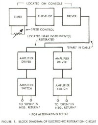
FIGURE 1. BLOCK DIAGRAM OF ELECTRONIC REITERATION CIRCUIT
The output of the flip-flop is a symmetrical square wave which turns the driver and the amplifiers on or off. The DC amplifier switches act as a single-pole, double-throw relay, but there are no arcing contacts to worry about and each amplifier switch will handle approximately three amperes of current. The reiteration speed control is like an ordinary volume control which controls the speed of the timer circuit.
The keyer unit is built on two 4"x4" printed circuit cards. The timer, flip-flop and driver circuits are on one card, and the other card is used for the DC amplifiers. The timer card should be mounted somewhere in the console, and the reiteration speed control can be placed within reach of the organist, or mounted on the card. This card may be used to drive a 12-volt relay, magnet, etc. The DC amplifier card should be located near the instrument being reiterated.
The keyer unit was designed to be used with the existing organ 12-volt DC power source where the positive side is the "hot line" and the negative is grounded. The DC power source should be well-regulated. The keyer unit will perform satisfactorily on between 10 to 15 volts. The timing card requires approximately 70 milliamperes and the amplifier card requires approximately 260 milliamperes.
Let us examine some of the various combinations as to how the keyer unit could be hooked up. One timing card can drive all DC amplifier cards, or there could be a timing card for each DC amplifier card. To reiterate one instrument, only one of the DC amplifier switches is used on a card. Both amplifier switches are used for the marimba effect or two instruments could be alternately reiterated from one card. To stop reiterating, a stop key, or switch, is needed to furnish 12 volts at 25 milliamperes to the amplifier card and then the instrument will play "single stroke." The DC amplifier card could be wired so that the two DC switches are not alternating but switching "in phase" with independent stop key control for each DC switch. This whole thing may seem complicated but really it isn't, and think what it will add to the organ!
Complete circuit diagram of the keyer unit, parts list, organ hook-up and notes grouping for the marimba effect are available free to the first fifty persons who send large self-addressed envelopes. If there is sufficient demand for etched circuit boards, the boards and instruction could be made available.
About this site © PSTOS, 1998-2004